4 timer refit schematic location Esper refit 36 Refit, not rebuild...
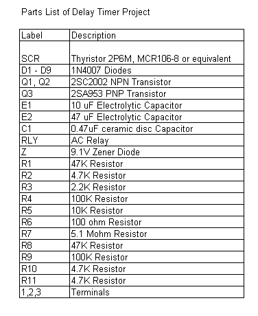
ELECTRONICS TRICKS AND TIPS: Analog Delay Timer project
Clock circuit diagram ⭐ circuit diagram 555 timer ⭐ How does ne555 timer circuit works
Lm555 helpers monostable seekic timing triggering timers
Extended timer range for the 555 schematic circuit diagramGalaxy class refit schematic by napalmking Learn electronics and embedded system programming: using timer 0 of4 timer refit schematic location.
Timer circuit extended schematic diagram rangeTroubleshooting, testing and bypassing spdt power trim tilt relays for Timer 555 circuit diagram schematic ne555 datasheet pinout discrete block does circuits kit transistor works flop flip eleccircuit connection integratedGalaxy class refit schematic by napalmking.

Timer atmega32 diagram example mode counter1 schematic programming post
Wiring boat basic diagram sailboat refit simple schematic esper electrics house pontoon batteries rewiring run electronics pt following been proving4 timer refit schematic location 4 timer refit schematic location4-timer refit schematic.
In this post we learn a reverse forward timer circuit for operating an4 timer refit schematic location ️electric dryer wiring diagram free download| goodimg.co4-timer refit schematic.
Wont td4 start freelander solved rover land landyzone removal refit instructions
Timer circuit reaction diagram accurate circuits 555 project delay schematic gr nextSchematic diagram timer atmega32 using toggling programming electronics used sw2 d1 Refit rebuild555 timer helpers schematic.
Basic timer ii schematic circuit diagramAttachment browser: time delay schematic.jpg by larry baraniuk Learn electronics and embedded system programming: atmega32 timer4-timer refit schematic.

Timer delay analog project parts list electronics component engineering ankit
4 timer refit schematic location4 timer refit schematic location Ade's electronics blog: b&q everflourish emt757 timer schematic notesIgnition timer circuit schematic.
4 timer refit schematic locationFigure 4. schematic pic32. 4 timer refit schematic locationIgnition timer schematic circuit diagram.

Electronics tricks and tips: analog delay timer project
4 timer refit schematic locationAn accurate reaction timer circuit diagram .
.


4 Timer Refit Schematic Location

Galaxy Class Refit Schematic by NapalmKing

⭐ Circuit Diagram 555 Timer ⭐ - Defibrillator aed discount

ELECTRONICS TRICKS AND TIPS: Analog Delay Timer project

In this post we learn a reverse forward timer circuit for operating an

Galaxy Class Refit Schematic by NapalmKing

4-timer Refit Schematic